From the very beginning, the Chinese Theatre has striven to give the public a good show. Part of this experience includes the projection room. From the silent era to IMAX®, the Chinese has played host to the entire range of motion picture technologies. This heritage is so illustrious, that a history of projection and sound reproduction systems just had to be compiled. We welcome readers to help flesh out this history, as it, while fascinating, is a most elusive subject.
Always looking for a way to outpace the other major studios, Universal Pictures joined the early 70s parade of disaster films with Earthquake, released in November of 1974. Earthquakeshared with other films like Airport and The Poseidon Adventure the all-star cast, widescreen photography, and “world gone mad” settings, but with one more thing: Sensurround.
It has been suggested that Sensurround was the star of Earthquake, and this might well be true. Universal had developed a system of what are now called “subwoofers” which were capable of raising the sound pressure levels in the theatre to the point where audience members would feel the vibrations of the air against their bodies. Since this was thought to simulate an earthquake, it was seen as a perfect accompaniment to a film about an earthquake.
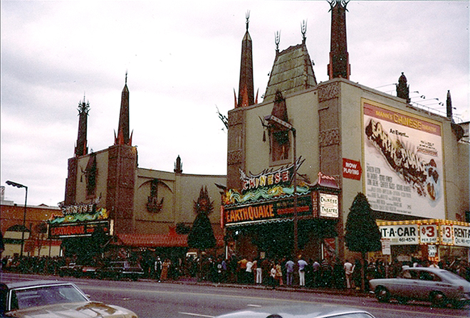
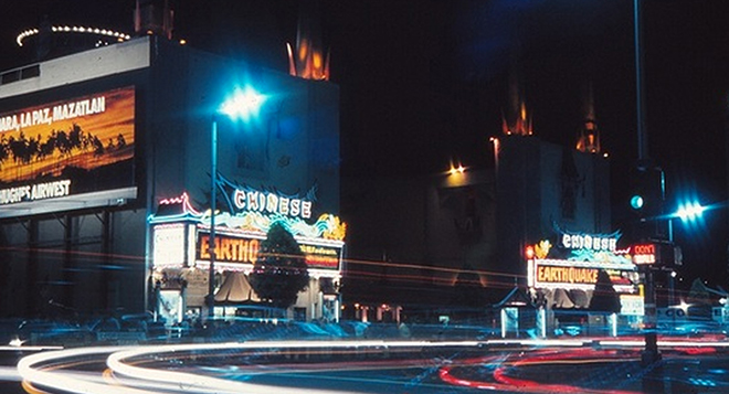
Mann’s Chinese Theatre, Hollywood, California. Exterior with lines waiting to see Earthquake, beginning November 15, 1974.
Of course today, we have all experienced this sonic effect whenever a car playing a deep subwoofer track drives by, rattling our windows. But in the mid-1970s, no one but audio buffs had heard what came to be known as infrasounds: sounds near or below the human hearing range. Earthquake was a hit worldwide, and started the race toward developing subwoofers for audio systems both in the theatre and in the home (or car).
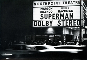
As with the installation of Hell’s Angels, the Sensurround installation at the Chinese was the World Premiere of this technology. But while Hell’s Angelsmade no mention of its sound system and Magnascope presentation, Universal hyped Sensurround in all of its advertising and publicity, and audiences agreed that feeling sound was a fun thing. Before long, the Dolby System people were looking to replicate the subwoofer action from Earthquake in a little picture they were working on called Star Wars. The rest is history as they say.
Prehistory
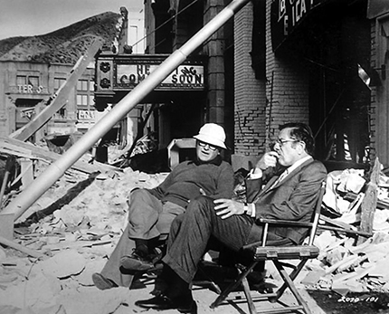
Executive Producer Jennings Lang with Producer / Director Mark Robson on the set of Earthquake, released in November, 1974. Publicity photo from Universal PIctures.
After the success of Airport (1970), Universal was looking for another film which told of a group of characters in peril. Working with executive producer Jennings Lang (1915-1996) and producer/director Mark Robson (1913-1978), and taking inspiration from the 1971 Sylmar earthquake in Los Angeles, an earthquake setting allowed for a larger canvas than the confined airplane interiors of Airport. The success of The Posiedon Adventure (1972) gave the picture a fast-track greenlight, requiring the Earthquake unit to work hard to open before that other pillar of the disaster film, The Towering Inferno (1974). As usual, producer Lang sought something which would give their project a little extra “something,” which couldn’t be experienced on television.
Universal studio general manager Joseph Hiatt called upon retired Universal sound director Waldon O. Watson to assist then-current sound director Richard J. Stumpf to brainstorm some way of convincingly recreating the sound of an earthquake. Watson became interested in working on the project because, years earlier, he had worked at Republic Pictures on a project that had an earthquake in it, the serial Adventures of Captain Marvel (1941), but optical sound technology at that time wouldn’t even come close to making a vibration sound that could be felt. What could accomplish this?
The Idea
Sounds are created by various things (transducers) which can change air currents. Hammers, butterfly wings, the glottis / larynx interaction of human speech — all these things create sound waves. If you are in a quiet room and someone speaks to you, the speaker creates a change in the sound pressure levels of the room. These are changes which your eardrum receives and sends as sounds to your nervous system and other organs in your body. The tone of a sound is measured in Hertz (Hz), while the loudness of the tone is described in Decibels (dB).
It is possible to create sound waves which the human ear cannot detect. Extremely high pressures and extremely low pressures. As low pressurized sound waves descend toward 0 Hz, the sound waves can no longer be heard, but they are still there. They can be felt as vibrations against the body. These low sounds have come to be called infrasounds.
Infrasounds are what audio and sound experts call sounds which are lower than what the human ear can detect — normally anything below 20 Hz. In order for the human ear to hear these low sounds, the sound pressure must be increased to the point where the vibrations can be felt as well as heard. These low-frequency infrasounds can cover great distances with little dissipation — perfect for a large theatre. Now, how do we get these low-level sounds from a conventional film soundtrack? MCA/Universal engineers were committed to utilizing one of the then-current film formats, so that theatres playing the film would not have to install new projection equipment, which would be a huge inducement to install Sensurround. The design parameter was to only add to what a theatre already had.
The best sound delivery systems for movie theaters at the time — magnetic prints — could not really reproduce frequencies below 40 Hz, but they were going to have to work with 35mm 4-track magnetic striped prints as their delivery method anyway. With the then-recent development of powerful subwoofer speakers and high-capacity amplifiers, it would be possible to create low frequency soundwaves of sufficient volume to vibrate the air in a large theatre full of people.
Subwoofers
A subwoofer is a speaker driver designed to produce bass tones of low frequencies — generally sound from 80 Hz and below. Subwoofers usually are several drivers mounted in beefy wooden cabinets or enclosures which can withstand the increased sound pressure without falling apart.
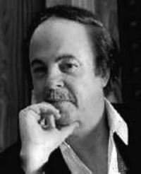
Arnold Nudell, no date, probably late 1970s. Via dh.yesky.com.
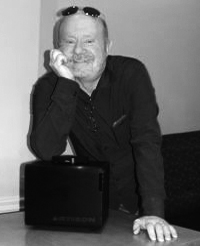
Cary Christie with Nano 1 subwoofer. Photograph by unknown, 2014. Via dealerscope.com.
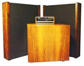
PR photograph of Infinity Servo Statik 1 system, introduced in 1968.
Subwoofers were invented in 1966 by physicist Arnold Nudell (born 1938) and Airline pilot Cary Christie in Nudell’s garage in Chatsworth, California. At the time, the biggest and lowest speaker on the market was Cerwin-Vega’s 18-inch driver. Cerwin-Vega had been founded in 1954 by Gene Czerwinski (1927-2010) as Vega Laboratories. Nudell and Christie had taken the Cerwin-Vega 18-inch driver, and given it a second winding, which would then send servo control information to the amp. The Servo Statik 1 speaker system was introduced by Nudell and Christie’s newly-formed Infinity company in 1968. It was a complete package: bass amp, crossover, two electrostatic midrange speaker arrays and a huge subwoofer aimed at the floor; it was hugely expensive.
Here was technology which could provide the infrasoundscape required for Earthquake. Universal allowed several speaker companies to make proposals for the Sensurround project, but the contract to build all the speaker drivers went to Cerwin-Vega. The 189 E — “E” for Earthquake — woofers were developed. The woofers were 18” inches, were rated for 400 watts (!) and folded into various horn configurations:
Model-C (Corner)
Model-W (Folded Bass Bin)
Model-M (Modular)
For these units to produce sounds as low as 18 Hz, the mouth of the horn cabinet had to be very large — that, or lengthen the path from the driver to the open air of the theatre. So a folded cabinet was designed, since the low frequencies did not suffer from degradation the way higher frequencies do. The Model-M horn design was used for the speakers to be arranged below and in front of the screen, since it had a fairly low profile.
Two Model-W cabinets were to be placed in the rear corners of the auditorium and would act as “surround” speakers. Placing them in the corner would allow the speaker to improve its ability to radiate sounds, due to the fact that the walls and floor and ceiling create a more limited area for the horn to deliver to — they act as an extension of the horn in a way.
Mann's Chinese Theatre, Hollywood California. First Floor Plan showing position of Sensurround speakers installed in November, 1974 for the engagement of Earthquake. As may be seen, the sound waves strike listeners from all directions, with the greatest concentration of impact in the center of the auditorium.
Low frequency sound effects in the 18-33 Hz range are difficult to reproduce for two reasons. Firstly, since most people cannot hear sounds that low, they must be over-amped in order to be audible to most people, and secondly, lower tones have a longer sustain or duration, and so, are harder to reproduce accurately.
With subwoofers, it is a challenge to have it all work together: amp, drivers and cabinets working with high volume without it all falling apart. Clipping (distortion) from the amp, rattling or unwanted resonance in the cabinets or “chuffing” sounds if the cabinet is ported are all things which can go wrong.
Cerwin-Vega received a lot of market acceptance from their subwoofer efforts, and today is a leading manufacturer of subwoofer systems for home, car, and professional use.
Amplifiers
Universal tapped BGW Systems of Hawthorne, California, to provide amps for the Sensurround system. BGW Systems had been founded in 1971 by Brian Gary Wachner (1945-1997), who had graduated with an electrical engineering degree from UC Berkeley. Talk about rags-to-riches; Wachner began making his heavy-duty amps for rock concert applications in his garage, while the day job was being a sales rep for National Semiconductor. It wasn’t until Universal tapped BGW to provide the amps needed for Earthquakethat he was able to devote all his time to making equipment.
BGW Systems Model 750A power amplifier. Introduced in 1974. Catalog photo. Via hifiengine.com.
BGW introduced its 750 line of professional solid state power amps for Sensurround, beginning with the 750A, and moving on to the 750B in short order. The 750s were of super heavy-duty construction, with an all-welded steel chassis. Originally designed for stereo, with 5-way binding posts on the back for speaker connections, the unit had a switchable bridging mode for use as a mono amp, providing 600 watts at 8 ohms. These units were also given forced air cooling systems, with a two-speed thermostatically-controlled fan mounted on the back, which drew air in, forcing it through “heat sink fins” and out of either side. While the Sensurround application demanded high levels of power, there was always the chance of blowing out a speaker driver.
So the 750s are outfitted with fast-acting circuit breakers, which would shut off the power to the speaker(s) if the power passed a pre-determined threshold. They weighed 54 pounds apiece. Connection to the speakers was through rubber jacketed twisted number 12 cable.
BGW hit the big time with Sensurround. The company went into supplying amps to movie theatres, discos, and theme parks. They also went into making heavy-duty touring amps for concert shows. On their web site, they say they will still hand-make you one of their 750A amplifiers if you want one — for $1,995.
Bring the Noise
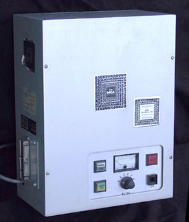
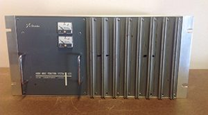
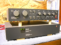
Sensurround Control Unit. Introduced in 1974. Photograph by Thomas Haureslev, via in70mm.com.
Now we have speakers and amps capable of replicating infrasonic sounds at very large sound pressure levels. Now what? Since 35mm 4-track magnetic can’t contain the low rumbly tones, how will we generate the earthquake noise and vibrations which is at the heart of the idea?
Follow this chain of events: for the earthquake rumble, it seems someone was able to make recordings of the 1971 Sylmar earthquake (how does one record an earthquake?), which were referenced to try to reconstruct the frequency and duration of the infrasound rumble. A man named D. Broads “Don” Keele, Jr. designed an "effects generator" which could randomly generate a signal which approximated the earthquake recording. It sounded random anyway.
When activated, the Effects Generator could send its random noise to the Sensurround Control Unit, which would co-ordinate the volume and placement of the noise.
The next step would be: how do we trigger the Control Unit for when we want it to make some noise? It was decided to utilize the optical soundtrack on the 35mm 4-track magnetic print. Since 1957 or so, this had been known as a “magoptical” print: the optical track carried a film’s stereo tracks in mono, so that the print could be run on a projector with only optical sound heads (provided that the projector had the smaller “Fox Hole” sprockets installed).
The optical soundtrack for Earthquakewas used to carry two types of control tones; one of 25 Hz and the other of 35 Hz. Using these two tones in various combinations would work like this:
35 Hz
Tone
25 Hz
Tone
State
Action
OFF
OFF
# 1
Play magnetic (program) tracks at normal volume.
ON
OFF
# 2
Activate the Effects Generator and Sensurround horns and boost program tracks 6 dB.
OFF
ON
# 3
Activate the Effects Generator and Sensurround horns with 6 dB boost, program tracks remain normal volume.
ON
ON
# 4
Activate the Effects Generator and Sensurround horns with 6 dB boost; boost 3 program tracks 6 dB; filter out program track channel 2 above 45 Hz and add to signals being sent to Sensurround amps and horns.
The signal coming from the optical track went directly to the frequency detectors in the Control Unit, bypassing the usual Academy filter, which had been in use at that time to try to give optical tracks better low-end performance, as well as any other equalization or low-pass filtering. The variable area image was configured in such a way as to provide pulses of light to the photo electric cell of the projector. Let’s say that the track would go from narrow (closed), to wide (open) in the space of one frame. Running at 24 frames per second, this track would send a 24 Hz tone to the Control Unit.
But since a 25 Hz tone was desired, this opening and closing on the track is in slightly LESS than one frame, raising the tone to 25 Hz. For 35 Hz control tones, the space is even less. Both of these signals could be placed on the optical track together, just like any other track would be — they were just mixed together.
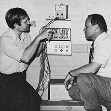
Academy Award Theatre, Los Angeles California. Robert Leonard and Richard Stumpf with the Sensurround Control Unit in the projection room, 1974. From American Cinematographer, November 1974, "Sensurround."
The signal level of the control tones could also be increased or lowered as desired in order to increase or diminish the loudness of whatever was selected for the Sensurround speakers to be doing. All of this was called the “Step-Gain” function. The filters looking for these two tones were considered sluggish, even with special dip filters, so the way around that problem was to place the control tones on the optical soundtrack slightly before they were desired, and let the lag in the filtering delay them so that they would be placed correctly. More movie magic.
It was discovered that when the rumble was being used, the rest of the soundtrack supplied through the 3 tracks of magnetic (program) sound (the effects channel having been disconnected) would get lost in the mix, so to speak. In State 2, yet another set of circuits would boost the regular tracks 6 dB when the rumble generator was on, this triggered by the control tones. State 3 did the opposite: the program tracks were left alone and the rumble sounds were increased. State 4 boosted everything.
The system could generate bass fundamentals down to 16 Hz at 100 dB — very low and very loud. This is VERY loud. It is about as loud as if you were to stand a few feet away from a jackhammer.
Universal initially set up a test simulation of the Sensurround system using concert bass speakers driven to 120 dB, then ran some noise through it and screened it with some of their effects shots for Earthquake, and showed them to people on the Universal Studios Tour. Response from these test subjects was positive, so the system was a go.
Sensurround at the Chinese
A total of 16 BGW 750A amplifiers running in mono mode were required to drive the Sensurround speakers, so several new racks full of them had to be installed in the projection room. Additional power for these units was needed as well, so a separate sub panel with one 20 amp circuit breaker for each 750A amp would have been set-up. Since each amp had a two-speed fan inside, they all made considerable noise.
Mann’s Chinese Theatre, Hollywood, California. Exterior during the engagement of Earthquake, beginning November 15, 1974. Photograph by ChasSmith, via Cinema Treasures.com.
Universal was able to convince theatres to book Earthquake in Sensurround by renting them all of the extra equipment, supposedly at $500 per week (we suspect it might have been higher for the Chinese). Later in the Sensurround program, theatre owners could buy the gear outright, with Universal shipping the Model-M speakers unassembled for extra convenience. Or they could buy the horns and Control Units and the plans for the cabinets and they could build the enclosures themselves! Engineers from RCA Technical Services performed all of the installations, ordering parts from MCA (Universal’s corporate parent company).
Mann's Chinese Theatre, Hollywood, California. Auditorium with 65' x 27' 'Scope masking settings. From Pictorial Souvenir of Mann's Chinese Theatre, Showplace of Hollywood, a "Colorpicture" Publication, Boston, Massechutetts, 1986. 35mm films wewre shown with the larger 70mm screen reduced to what is shown here. Earthquake would have been shown at this size.
Since the installation of Sensurround at the Chinese was the first ever attempted in a commercial theatre, the problems encountered must have been considerable, and time consuming to correct. Nearly every theatre experienced some sort of difficulty, since the Sensurround units were having to interface with a theatre’s existing sound set-up — whatever that might consist of.
Manuals and other documentation from the Sensurround period contain many descriptions of problems installers encountered when installing the gear. At this point in movie history, nearly every theatre had a different arrangement of projectors, soundheads, preamps, equalizers, speakers and on and on. RCA tech people in the field would compile their solutions to set-up problems and these would be included in the new edition of the set-up manuals — something that would be done on the internet today, no doubt.
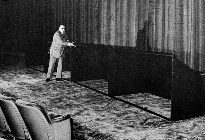
Mann's Chinese Theatre, Hollywood. California. Waldon O. Watson and Model M Sensurround Horns at the front of the auditorium, 1974. From American Cinematographer, November 1974, "Sensurround." American Cinematographer states that the horn configuration seen in this picture was deemed "too loud" for the front row of seats, and was changed for horns on either side of the screen, but accoring to eyewitness accounts, this is the configuration used during the run of Earthquake at the Chinese.
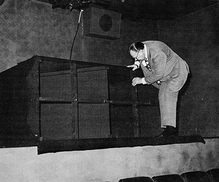
Mann's Chinese Theatre, Hollywood. California. Waldon O. Watson and Model W Sensurround Horn at the house left rear corner of the auditorium, 1974. From American Cinematographer, November 1974, "Sensurround." The speakers were installed on wooden platforms covering two rows of elevated seating which had been created during the Cinemiracle remodelling in 1958. Note the Altec Lansing 629 "auditorium" speaker as well as the cable for the sensurround speaker punching through a hole in the ceiling.
Once set up, the installation crew had to adjust the system so that sound pressure levels of at least 95 dB were measured in the center of the theatre, while corners should not exceed 110 dB if standing 4 feet from a horn. The Sensurround Installation Manuals claim that “these levels are safe for human consumption continuously for periods of up to 8 hours (Huh? What’s that you say?)” Remember that the tones coming from the Sensurround speakers went down as low as 16 Hz at 100 dB. It was theorized that, since buildings don’t begin to resonate until you get down to 6 Hz, the Chinese would be safe. In a brilliant stoke of genius though, a safety net was installed over the central part of the ceiling to catch anything which might fall loose.
Although it was probably insisted upon by those marvelous people at the insurance companies, there was never any damage done to the Chinese during the run of Earthquake. But the net was an awesome come-on before the film — is this place going to fall down?
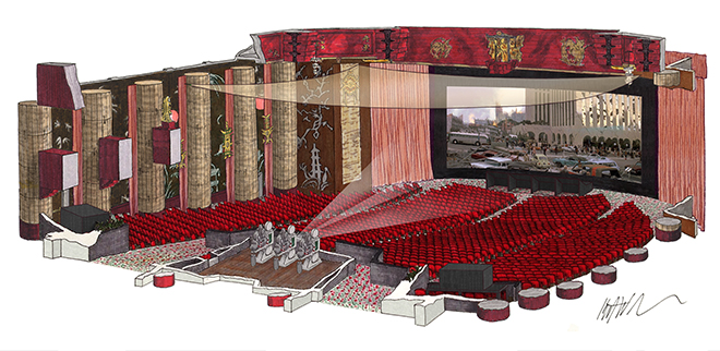
Mann's Chinese Theatre, Hollywood, California. Auditorium showing position of Sensurround speakers and safety net over the audience, 1974. Drawing by Kurt Wahlner.
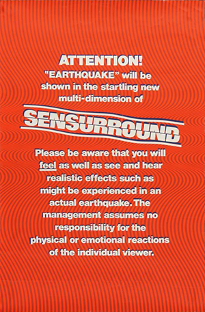
Teaser poster for the film Earthquake, released in November, 1974. 27 inches x 41 inches. This poster was used to "warn" patrons before heading into the auditorium. They were silk screened on heavy paper and rolled, so many of them became damaged and are quite rare today.
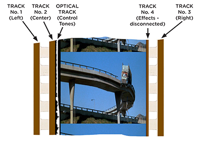
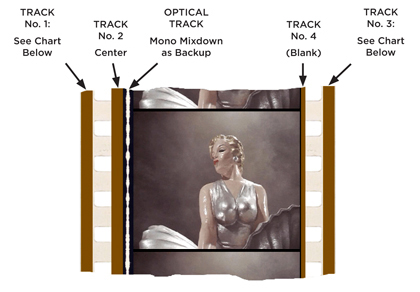
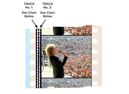
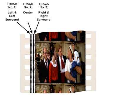
Earthquakewas run at the Chinese with the 35mm "dual” print, with the optical track carrying the control tones for the Sensurround functions. During times when it was desired to send some of the film’s soundtrack to the Sensurround speakers, only track 2 (center) was used. It seems that Earthquake’s dialog was all contained on the center channel, rather than panning it across the 3 speakers behind the screen. Track 4, for the effects speakers, was recorded with the standard 12 kHz control tone used to turn the effects channel off when not needed in order to reduce hiss in the system.
However: It was dictated that Track 4 should be disconnected. The surround channel was there and recorded as normal, but this was so that a theatre without Sensurround gear could play the print. At the Chinese, the effects channel, track 4, was not used. Since there were two honkin’ Sensurround speakers in the corners of the auditorium, there was plenty of effects ambience.
Initially installed in only 17 theatres, it is said that Earthquakeplayed in nearly 300 theatres in the U.S. before the end of its theatrical run. RCA trained their installers corps in the mechanics of the Sensurround gear while Earthquakewas playing its first 17 engagements, so many, many trainees were brought through the Chinese before they were able to make Sensurround installations in the Southwest of the U.S. and, presumably Hawaii and Asia.
The Aftermath
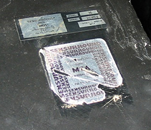
Identification labels on Sensurround Model M Cabinet. 48" x 48" x 20". Introduced in 1974. Nearly 250 pounds. Photos by whiskey_face, 2010. Via ilovefuzz.com.
After Earthquake, the career path for Sensurround was somewhat limited. Although Earthquakehad been a hit, running 17 weeks at the Chinese, with several theatres in the Los Angeles market playing the film in 4-track Sensurround after the Chinese engagement, the public had a “what will they do for an encore?” attitude toward the system. How many films during that period could use a rumble track?
Filmmakers today would argue “all of them,” but at this time in the mid-70s, Universal’s management of Sensurround was one of turmoil. The history of Sensurround has yet to be written, but a chapter on market acceptance would show a considerable success — for a time. But as a 4-track mag only system, Universal saw the handwriting on the wall: make it less expensive.
In response, the first thing they did was to try to figure out a way to have the system do all of the things required using only optical soundtrack prints. This demanded considerable re-jiggering of things, which resulted in the Sensurround Mod-II system, used for the films Midway (1976) and Rollercoaster (1977). Universal had typically misread the market, since its mega-hit Jaws (1975) could have used the rumble, as long as it wasn’t the main selling point, and Star Wars (1977) released the same time as Rollercoaster, clobbered the Sensurround experience with its 70mm Dolby “Baby Boom” subwoofer channels that they weren’t even promoting.
Then, Sensurround Mod-III came along. The point of this revision is somewhat obscure (even to us), but the objective was to try to increase the frequency range of the optical delivery system in order to make the rumble and effects louder. This was followed by Sensurround Plus for Zoot Suit (1981), released in 70mm, which used dbx noise reduction to reduce tape hiss. We "hear" a good deal about Dolby System here at the end of our Sensurround section, so Dolby Labs is our next port o’ call.
The Dolby Systems: 1976-Present
What could be called the first big “blockbuster” film of the more modern usage of the term, Jaws, was released in the summer of 1975 in 35mm ‘Scope with optical mono sound. And as good as it sounded, it was clear that the “Film Brats” visuals were outpacing theatre sound conventions. The solution appeared just two summers later with the release of Star Wars, when the Dolby name emerged from the shadows of Kubrick's A Clockwork Orange, and took right, left and center stage. With surrounds. The phrase “Dolby Stereo” came to signify a whole new era of picture making.
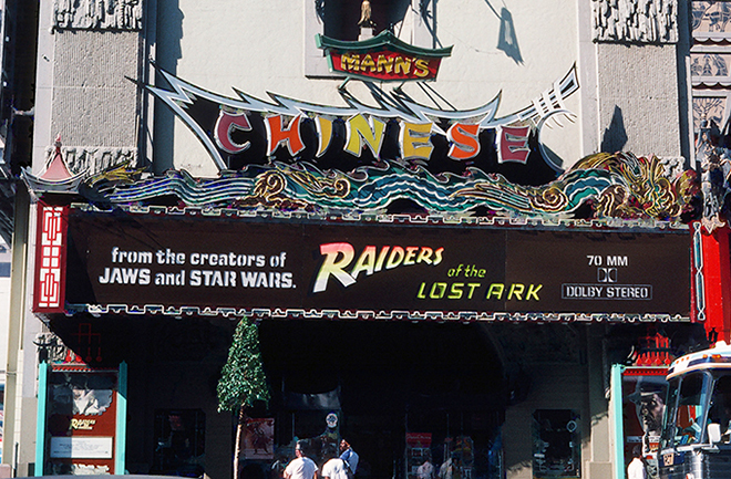
Mann's Chinese Theatre, Hollywood, California. Exterior during engagement of Raiders of the Lost Ark, beginning Friday, June 12, 1981. Photograph by David M. Hunter.
The story of the Dolby Systems is a complicated tale, involving technology, filmmaking, Hollywood, film processing labs, upgrades, software, hardware, “branding” and all of the wonderful things which have brought us to where we are today. The Chinese Theatre, as usual, has played a significant role in the development and marketing of not only the Dolby systems, but of the THX program as well. In terms of brand recognition, both of these technologies have far surpassed that of any previous film technology—with the possible exception of Technicolor or Kodak—and yet, their day may be waning—theatrically anyway.
The Beginnings
In the beginning, there was the noise. In any of the recording mediums we have discussed in our survey here, whether optical or magnetic, background noise is always present. Different systems make different background noise; this difference is measured and referred to as the “signal to noise ratio.” Magnetic recording was able to trump optical recording because magnetic’s background noise was lower, and thus, the signal to noise ratio increased.
But even still, the delivery of multi-channel sound in theatres via magnetic tracks always contained what came to be called “tape hiss,” which is the background noise inherent in these devices. It sounds like air escaping a tire — it hissess. Manufacturers of magnetic recording and playback devices sought to decrease the hiss in their systems as a way to establish technical superiority — and to charge more money for it, of course.
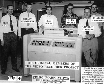
Fred Pfost, Shelby Henderson, Ray Dolby, Alex Maxey, Charles Ginsburg and Charlie Anderson pose with the Ampex Mark IV at the Ampex research lab in San Carlos, California, 1956. Photo from First-Hand: My Ten Years at Ampex and the Development of the video recorder by Fred Pfost, posted on the Engineering and Technology History Wiki: www.ethw.org.
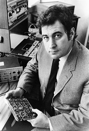
Enter, Ray Dolby. Born in Portland, Oregon in 1933, Dolby became fascinated with sounds and played the piano and clarinet as a child. After World War II, the Dolby family moved to the Bay Area, where the movie-mad young man got a job as a projectionist in a local theatre. By 1951, Dolby had met and impressed Ampex founder Alex Poniatoff, who offered him a job working on their 200A magnetic tape recorder. While attending Stanford, Dolby served as a “consultant” at Ampex, joining a team of engineers who were trying to develop a way to record video and audio signals onto magnetic tape. This project was sidelined while Ampex developed multi-channel amplification systems for CinemaScope and Todd-AO installations.
In 1953, Dolby lost his draft deferment because he was working full-time at Ampex and was no longer attending Stanford. He served in the U.S. Army, and in early 1955, resumed his studies at Stanford. He also did part-time work at Ampex, which had returned to the video project. The task of magnetically writing video along with audio signals onto 2-inch magnetic tape was daunting. Dolby designed a multivibrator oscillator, which could receive the composite video signal, and using frequency modulation, fit all of the information into the carrier signal on the tape. Dolby also worked on the processing amplifier, which was used to convert the video signal to be fully compliant with broadcast video standards. The Mark IV — the world’s first video recorder — made its debut in 1956, and became, even at $50,000 each, a huge seller.
After that, Dolby graduated with a B.S. in electrical engineering from Stanford. He won a scholarship to obtain a Ph.D. in physics at Cambridge’s Pembroke College in England, where he graduated in 1961. While there, Dolby had learned about a UNESCO project which was recording indigenous music from around the world. Dolby got involved and was sent to India to record Indian classical and folkloric music in Uttar Pradesh and Punjab. Dolby became unhappy with the tape hiss in the recordings, which were augmented by a noisy ceiling fan located in one of the recording locations. Looking for a solution to this background noise problem, Dolby returned to England in 1965, where he opened Dolby Laboratories on a shoestring, introducing the Dolby Audio Noise Reduction System A301 unit that same year in November.
Dolby Noise Reduction
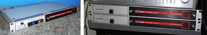
Dolby Laboritories Audio Noise Reduction System A301 unit. Introduced in November, 1965. Unit serial number #25, formerly belonging to CBS Records, New York, New York. Photo via eBay seller stereo-niche.
Dolby noise reduction could only have been invented by someone who, like Dolby, was familliar with the principle of the anamorphic lens used in CinemaScope and Panavision: take the thing you got and turn it into the thing you want.
As we have mentioned, magnetic recordings have an inherent hiss, which is magnified when there are more tracks. Tape hiss has to do with the iron oxide granuals in the magnetic “emulsion” of the magnetic recording medium. Tape hiss is most apparent when the sound levels are low, and nowhere near as noticeable when the signal is louder. Manufacturers discovered that the faster the medium ran past the recording and playback heads, the quieter the hiss became.
This, however, would not help the movie makers, who needed to synchronize the sound medium with the picture — both had to run at the same speed. To raise the signal-to-noise ratio in magnetic recording, regardless of the speed of the tape — was what Dolby was after. The Dolby A Noise Reduction System was introduced to the professional recording trade in Britain in 1965, and was immediately adopted by Decca Records, and very shortly thereafter by recording studios worldwide.
Dolby A, as it came to be called, works like this:
Tape hiss is most noticeable when volume levels are low. The Dolby A unit takes the incoming audio signal, and divides its frequencies into four sections, ranging from Low (80 Hz and below), Medium (80 Hz to 3 kHz), High (3 kHz to 9 kHz), and Extra-High (9kHz and above). Depending on the volume level, the signal is recorded louder than normal. This became known as “preemphasis.” When the volume levels drop, the preemphasis is increased.
A. Any recording medium has background noise.
B. Noise is only a problem when the sound is quiet.
C. Before recording, the Dolby system raises the levels of the quietest sound.
D. When the recording is played, the system restores the correct levels, reducing the noise in these places at the same time.
Diagram demonstrating Dolby Noise Reduction in the promotional brochure 364 Cinema Noise Reduction Unit and E2 Cinema Equalizer, published by Dolby Laboratories Inc, London England, 1975. Via www.film-tech.com.
Then, when this recording is played back, the same thing happens in reverse: the incoming signal is split into fours again, only this time, the parts which were recorded too loud are reduced in volume back to their normal levels. When this happens, the volume of the tape hiss is reduced as well, and voilà! Less tape hiss! This came to be known as “deemphasis.” It also made Dolby a fortune.
Dolby Noise Reduction and the Movies
It didn’t take long for techno-whiz Stanley Kubrick (who was living in Britain) to become interested in Dolby A noise reduction. Somehow, they missed the boat for 2001: A Space Odyssey (1968), but his next film, A Clockwork Orange (1971), became the first film to use Dolby A noise reduction throughout the entire sound recording process.
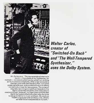
Wendy Carlos appearing in a promotional page for the Dolby System, circa 1969.
Meanwhile, in the U.S., it was a good thing that electronic music pioneer Wendy Carlos had been using Dolby A for her Switched-on Bach album in 1968. Carlos had been working on a piece called “Timesteps” inspired by her reading Anthony Burgess’ novel, A Clockwork Orange. She sent a preliminary recording of it and the “Ode to Joy” from Beethoven’s Ninth Symphony to Kubrick, then editing the film version, who immediately asked Carlos to join the production. Everybody using Dolby A, you see?
Too bad the release prints of Clockwork were standard 35mm optical. Dolby became interested in applying the same Dolby A noise reduction principles to the optical soundtracks used in films worldwide since the introduction of sound in 1927. Dolby recognized that sound delivered in theatres via an optical soundtrack were lagging behind the music reproduction systems in most people’s homes, while at the same time, most of the studios were severely reducing the number of films released with magnetic soundtracks.
In 1972, Dolby Labs introduced “The Dolby System” the 364 Cinema Noise Reduction Unit along with the E2 Equalizer. In addition to noise reduction, these two units did something else too — it expanded the frequency range of what could be produced on an optical soundtrack though the same method of compressing the wider frequency range of magnetic recordings into the more limited range of optical. The E2 Equalizer Unit allowed realtime adjustments to the soundtrack based on the specific acoustics of a given theatre. Dolby offered that their tecnicians could set up and adjust the Equalizer to suit the sound qualities of each theatre.
ABOVE LEFT: Dolby System 364 Cinema Noise Reduction Unit. Introduced in February, 1972. ABOVE RIGHT: Two Dolby System E2 Equalizer Units. Both introduced in September, 1973.
The result was incredible — but in mono. Although the 364/E2 units could and did play regular optical tracks as well as magnetic prints, the best results were obtained when used with a Dolby-compatible print, and even though all the film producers in Hollywood and Britain were using Dolby A noise reduction, few wanted to go the extra mile and produce release prints in this format.
The lacklustre reception of the 364/E2 units by the film industry didn’t stop Dolby Labs one bit. They had their fingers in a great number of pies, from licensing their noise-reduction technology to consumer electronics companies to applying Dolby NR techniques to FM broadcasting signals.
A real breakthrough in our story occurred when Ron Uhlig, an engineer at Eastman Kodak, created a method where two separate channels could be created out of the conventional dual bilateral variable area optical soundtracks, which had become standard for film prints since the mid-1950s. The project had been initiated by the legendary sound engineer Dr. John Frayne along with Kodak and RCA. Uhlig had achieved his success while trying to provide English and Spanish soundtracks on a single 16mm print. He had been using Dolby A, which caught the attention of Dolby Labs: You're doing what ??
After Dolby Labs became involved, it seems that a number of British-based companies got involved with developing what came to be called "SVA" for "Stereo Variable Area" soundtracks. Of course, this would require pulling out the old single-channel sound heads in your projector and replacing them with a dual-channel soundhead and preamps. Everyone wanted to apply the Dolby 364 system to improve frequency range, but still, this approach would only yield two channels.
Around the same time, audio engineers were looking for a way to deliver four channels of audio “quad” via 2-channel tape or vinyl disc. One technique which showed promise was to “matrix” audio signals — to create four channels from only two. Sansui of Japan took the market lead with their Sansui QS Encoders and Decoders.
“Matrixing” is when two channels of sound are recorded onto one track, with one channel recorded in phase, while the other is recorded out of phase. To pull the two channels back out again, circuitry detects the signal which is out of phase, and separates it from the signal which is in phase, and there you have two channels again.
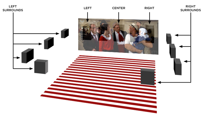
When director Ken Russell was brought onboard to make a film version of the rock-opera Tommy, he wanted the very loudest rock-concert type sound to come from all around the theatre. Recording engineer John Mosley was charged with designing a system, which could do this with more-or-less available parts. This included three concert-style speakers behind the screen, with another two in the rear (or four if presented in a theatre with a balcony). If this sounds familiar, it should, since what came to be called “Quintaphonic Sound” is a forerunner of what came to be called “Dolby Stereo.”
The five channels of the Quintaphonic Sound system were derived from a standard 35mm 4-track mag print. Two tracks used Sansui’s QS Matrixing technology to create four channels: Track One for the front and rear left (plus lower levels of the front right and rear right, recorded + 90 dregrees out of phase), and Track Three for the front and rear right (plus lower levels of the front left and rear left, recorded - 90 degrees out of phase). Track Two was used for the center channel, which is where they placed most of the singing and all of the dialog. Track Four was not used. QS matrixing relied on using low level out of phase signals from the left on the right and vice-versa in order to make a more sonically convincing dimensionality to the soundscape.
In addition, a company called dbx, Inc. had entered the noise reduction field in 1971. dbx had been selected over Dolby by Mosley to provide noise reduction for the mag prints of Tommy, as the dbx system “companded” incoming signals, which means that the frequency range is compressed and recorded, then, on playback, expanded to its full frequency range, while somehow reducing background noise.
This greatly increased frequency range capacity was considered important, because rock recording equipment could now deliver a wider frequency range than what 35mm mag prints could deliver. The arena-style rock concert sound system could deliver astonishing dynamics. The Tommy Quintaphonic Sound scheme was presented to theatre owners at a trade screening held at the Fox Whilshire Theatre in Beverly Hills, California, on February 6, 1975, then opened to the public on March 19. The soundtrack for the film was played at unheard-of levels, which perfectly matched the film’s manic — well — everything.
Leicester Square Theatre, London, England, Projection room, Quintaphonic amplifier rack for Tommy, March - December 1975. Photo courtesy of CinePhoto.co.uk.
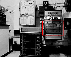
However, in Britain, Dolby’s Ioan Allen was knocking on the projection room door. Dolby had developed a unit they were calling the CP100 Cinema Processor. This unit did everything the 364 Cinema Noise Reduction Unit did, only it did it in multi-channel, and was capable of handling Dolby A encoded magnetic prints in either mono or stereo, optical mono prints, and most importantly, the newly developing “Stereo Variable Area” (SVA) stereo optical soundtracks. The CP100 was utilized for multi-channel noise reduction for the London engagement of Tommy at the Leicester Square Theatre, and this got the Dolby foot in the door.
Dolby had developed their work on delivering three channels of sound from the two variable area tracks (SVA), and showed it to Ken Russell and producer David Puttnam, who decided to use the “Dolby Stereo” system for Lisztomania, set to premiere in the U.S. in October of 1975.
It is important to note that Dolby Stereo at this point is a 3-channel system. The way it works is the following:
On the SVA optical track, there are two channels, right and left. Sounds intended for the right speaker goes on the right track, and sounds for the left speaker go on the left track. Sounds intended for the center speaker are recorded at the same level on both tracks. Logic circuitry in the CP100 detects this replication, isolates it, and sends it to the center speaker. At the same time, this center channel information is subtracted from both the right and left channels, which are then sent to their appropriate speakers.
To improve channel separation, “steering” was added: when the center channel signal was dominant, it was “boosted” 2 dB, while the left and right channel were dropped 2 dB. When the left and right channels dominated, they would get boosted, while the center channel would get toned down 2 dB. This “steering” handling would have a decided effect on the way Dolby Stereo in SVA would be mixed by people making films utilizing the system.
Now, we had it all from a regular old 35mm optical print: three channels of high-fidelity sound with hardly any background noise. A miracle, really. This perfection would not last long.
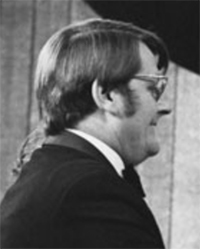
Ray Dolby circa 1974. From Remembering Ray Dolby: A Life of Innovation by Debra Kaufman, posted on CreativeCOW.net.
In January of 1976, Ray Dolby returned to his roots, moving his company headquarters to San Francisco, California, located at 731 Sansome Street. This move would have a profound effect on the company’s involvement with motion picture sound. Through the company’s office in Hollywood came an eventful call; the producers of the then-filming musical remake of A Star Is Born, wanted a slight change to the Dolby Stereo format: an effects channel.
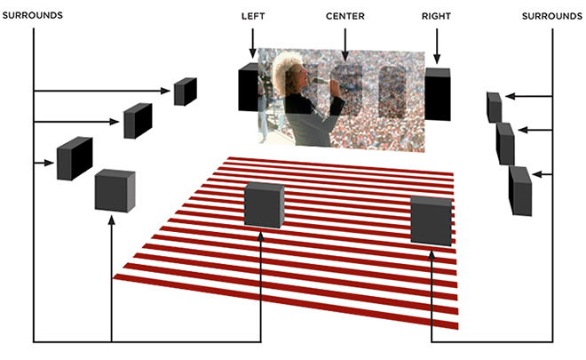
Since this version of A Star Is Born takes place in the world of rock music, all of the picture’s musical numbers were being filmed in live concert settings. To replicate the concert experience of the performers on the screen "surrounded" by an audience, the sound department wanted to utilize the effects tracks commonly used with 70mm magnetic and 35mm magnetic prints. But the three-channel Dolby Stereo wouldn’t allow for this; could Dolby Labs do something about adding surrounds to 35mm Dolby Stereo?
They didn’t want to, but they could.
The three-channel version of Dolby Stereo, which derived three channels from the two tracks on the SVA optical soundtrack was a slick item. Dolby and his team were proud of what they had accomplished and were reluctant to mess with it. But the clock was ticking; A Star Is Born was set to be released at the end of 1976. How would they add an effects channel? By licensing Sansui’s QS matrixing, which had been used on Tommy.
Since the QS decoder looks for material on the track which is out of phase, it was decided to place the effects channel + 90 degrees out of phase onto the left SVA track, and - 90 degrees out of phase on the right SVA track. Additional logic circuits attached to the CP100 unit (the SA2 Surround Sound Adaptor) would now look for out of phase material from both of the SVA tracks, isolate it, drop the rest, and send these signals along to the surround speakers with a slight time delay, adjustable depending on the size of the house. The delay would reduce the effect of crosstalk (signals from one channel leaking into another), since the leaking sound would come from the screen first, which is where the listener would think the sound was coming from. This is called the Haas Effect.
Track 1
Channel Information
Result
Right
Isolated and set to right speaker; if dominant, level boosted 2 dB; if not dominant, level dropped 2 dB
Center
(Identical with Center on Track 2)
Isolated and set to center speaker; if dominant, level boosted 2 dB; if not dominant, level dropped 2 dB
Surround ( - 90º Phase Shift)
Isolated, and after user-defined delay, sent to surround speakers
Track 2
Channel Information
Result
Left
Isolated and set to left speaker; if dominant, level boosted 2 dB; if not dominant, level dropped 2 dB
Center
(Identical with Center on Track 1)
Isolated and set to center speaker; if dominant, level boosted 2 dB; if not dominant, level dropped 2 dB
Surround ( + 90º Phase Shift)
Isolated, and after user-defined delay, sent to surround speakers
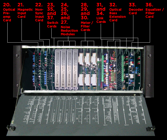
Dolby had developed the CP100 to be a “do everything” processor for all film sound formats (optical, 4-track mag, 6-track mag, etc.), combining both noise reduction and real-time equalization, as well as changeover circuits, automation, and easy format source selection. One could play regular audio recordings through it, and one could plug in a PA microphone. It was all designed to be a modular system, containing expansion slots for modules, allowing for different functionality in the future.
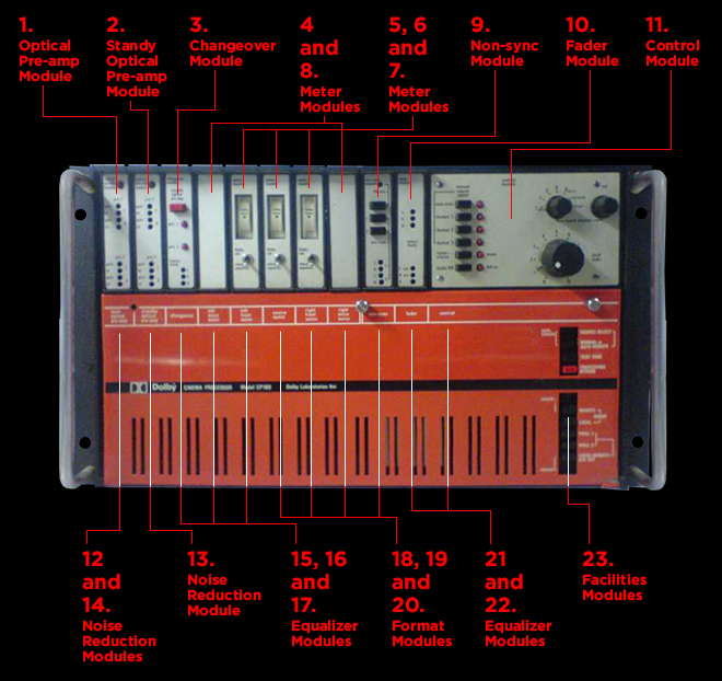
Although the Dolby Stereo format was originally set up as three channels, adding the Surround channel to it was a matter of adding a Pentopical Module (Catalog number 94) in one of the Format Module slots (18, 19, or 20) of the CP100, which would send signals to be handled by the outboard SA2 Surround Sound Adaptor, which was a separate unit containing the Surround Decoder Module (Catalog number 116). Full Disclosure of the CP100 follows below:
TOP PORTION:
1. Optical Pre-ampModule: Four inputs allow for incoming signals from 2 SVA tracks coming from two projectors. Front panel adjustment of gain and high frequency (Catalog number 75).
2. Standby Optical Pre-amp Module: Duplicate of #1 Module, used for emergency backup by pressing red button on #3; both modules have red indicator lights showing which pre-amp module is being used (Catalog number 75).
3. Changeover Module: Contains circuitry necessary to switch between projectors, with indicator lights on the front panel; rectangular red button toggles between optical pre-amp modules.
4 and 8. Meter Modules: Used for 6 track magnetic. These would indicate incoming levels for 70mm tracks 2 (left extra), and 4 (right extra). CP100 normally shiped with these slots empty.
5, 6 and 7. Meter Modules: Incoming level indicators for Left and Right channels from the SVA track or for 4 or 6 track magnetic, Left, Center and Right channels. Used to calibrate levels using Dolby Tone Loops.
9. Non-sync Module: Three inputs allow for stereo inputs as well as mono public address microphone; selector on # 11, the Control Module, selects this source.
10. Fader Module: Controls volume output levels for all incoming channels. The module contains six channels. Fader action is by a single control (on the control module # 11, or remotely situated) feeding all six electronic faders, whose present controls allow individual setting of the output levels to suit the power amplifiers in use.
11. Control Module: Module selects the source and its mode. Choose between non-sync (# 9), or one of the three "formats" which are plugged into slots # 18, # 19, and # 20 below. Select also for Dolby Noise Reduction or no, as well as volume control for the monitor speaker in the booth.
LOWER PORTION:
12 and 14. Noise Reduction Modules: Two noise reduction modules (Catalog number 22) decoding two inputs — the two tracks from the SVA soundtrack coming from the selected projector. One this was done, all derived or matrixed channels were already deemphasised. These could be used for two channels from either 35mm or 70mm magnetic prints.
13. Noise Reduction Module: Position for a third noise reduction module to decode a third track (used for 4-track magnetic prints). For six-track-encoded magnetic prints exterinal noise reduction units can be used for decoding.
15, 16, and 17. Equalizer Modules: Three 27-band third-octave equalizers (Catalog number 64) for Left, Center and Right channels.
18, 19, and 20. Format Modules: Units containing elctronics set up for individual formats, such as: A: Mono-Stereo Optical Module (Catalog number 82), which derives Left Center and Right channels from the two channel SVA track, also performs the "steering"; or B: Magnetic Tracks Module (Catalog number 84) for use with 4 track 35mm or 6 track 70mm prints; or C: External Format Module (Catalog number 83), which allows external connection for other formats yet devised. Format is selected via # 11, above.
21, and 22. Equalizer Modules: Two more 27-band third-octave equalizers (Catalog number 64) for Left Extra, and Right Extra channels; for the surround channel for either 4 or 6 track prints, a connection may be made with the single channel E2 Equalizer Unit.
23. Facilities Module: Module allowing for master control coming into the CP100, whether manual oreration or automatic programming or remote control Catalog number 88); includes a bypass switch in case of CP100 failure; may also be connected (via Catalog number 91) to emergency backup battery system.
Dolby Laboritories Cinema Processor Model CP100. Introduced in late 1975. 19 inches wide x 10.5 inches high x 11 inches deep; 36 pounds. Rescued from the Cineramakino, Zurich, Switzerland. From the collection of Magnus Rindisbacher, Dietikon, Switzerland.
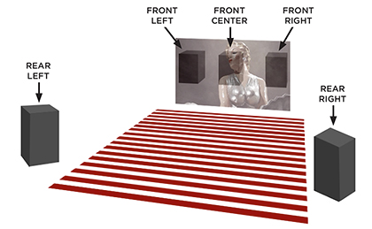
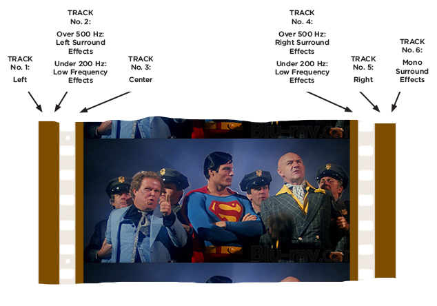
It didn’t stop there. Warner Bros., the studio releasing A Star Is Born, wanted to have Dolby encoded 70mm magnetic prints for the World premiere engagements of the film at Mann's Village Theatre in Westwood and Mann’s Chinese Theatre in Hollywood. The sound was being mixed in four channels (left, center, right, surround), what would they do with the 6 channels available in 70mm (1. left, 2. left extra, 3. center, 4. right extra, 5. right, 6. effects)? Although the film was meant to be shown in 1:1.85, and since this narrower image was placed inside the wider 70mm frame, the full array of 5 speakers weren’t needed. But industry practice at that time for converting 4-tracks to 6-tracks was to leave track 2 and 4 blank. The left and right channel would then go to the outer speakers for better separation.
Even so, the CP100 did not “do everything.” It had onboard pre-amps for the optical SVA only. One still needed the usual chain of pre-amps for all six channels for 70mm (for four channel magnetic as well). The CP100 didn’t contain enough slots for Dolby Noise Reduction modules or equalization modules to handle all six tracks either. For noise reduction modules, there were only three slots in the CP100. To do Dolby Noise Reduction on all six tracks, three additional 364 Noise Reduction Units would have to be installed.
For 70mm calibration, one would install additional Meter Modules into slots 4 and 8. Since the 364 Noise Reduction Unit patched in had an incoming signal meter, all six tracks could now be displayed while the Dolby Test Loops were played and adjusted for the proper balance. If equalizing the surrounds was desired (it usually was skipped), and additional E2 Equalizer Unit could be added to the chain.
It is again important to remember that even though the 70mm format with Dolby A Noise Reduction provided a quieter listening experience with slightly greater headroom in the higher frenquencies, the dynamic range of the magnetic print was enough — for now.
When Dolby showed the 70mm tests of the system back at the home office in San Francisco, some techno wonks told their boss about it — they thought it would be good for a picture they were working on called Star Wars.
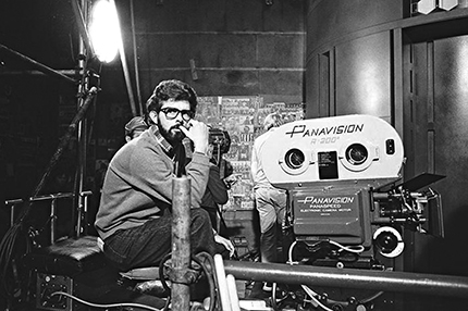
George Lucas on the set of Star Wars at Elstree Studios, Borehamwood, Hertfordshire, England, UK, circa 1976. via starwars.wikia.com.
It is quite probable that George Lucas and his Star Wars team had been aware of Dolby Stereo for some time — and as was usual for Lucas, sound played an important role in the space fantasy he was making for 20th Century-Fox.
A legend has attached itself to the first of the Star Wars films. The legend says that no one knew Star Wars would become a mega-hit. The legend may be true to some degree, but it has to be admitted that Lucas had learned his lesson well; he did what Walt Disney always did: he constantly looked for some way to “plus” his film.
In addition to one of the greatest music scores ever written and a robot character who communicated through a series of bizarre electronic sounds, this was a film filled with battle scenes, huge explosions, and other arresting audio effects.
When the Star Wars team looked at what was being done with what was being called “70mm Dolby System Stereophonic Sound” they noticed that tracks 2 and 4 on the print were not being used. What could be done with those?
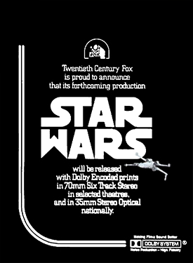
Trade ad announcing Dolby participation in release of Star Wars, from the Monday, December 6, 1976 issue of Daily Variety.
We may safely assume that many of the Star Wars creative team had seen Earthquake, released 2 years earlier, with its Sensurround effects, and which had been used to good effect in a war picture, Universal’s Midway (1976). Star Wars producer Gary Kurtz wanted to license Sensurround to use with the film, but Universal wanted a huge advance and a share of the gross.
Kurtz and Lucas met with Stephen Katz, Dolby's consultant liaison with filmmakers, who told them that Sensurround was crap. Its soundtrack-triggered effects generator only made a limited range of admittedly great rumbly sounds. Why not use these unused tracks on a 70mm print to carry a more nuanced version of Sensurround?
Dolby Labs devised a setup which would allow for two channels of sounds which could contain a lower frequency range than normal. Lucas had his sound effects team give the effects plenty of low end rumble, and this was achievable though the use of synthesizers and equalization technology.
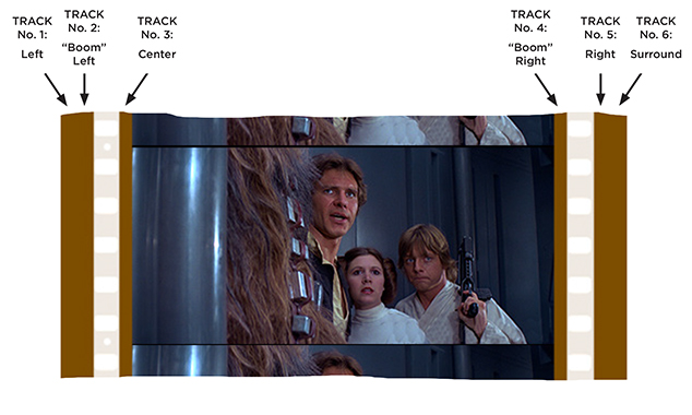
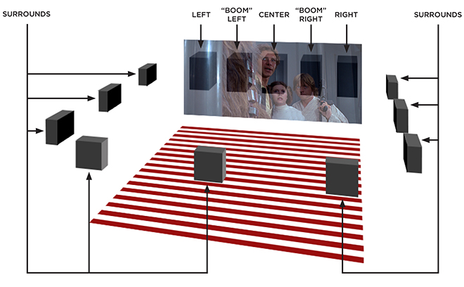
The result came to be called the 70mm “baby boom” format, which would become known as "Format 42."
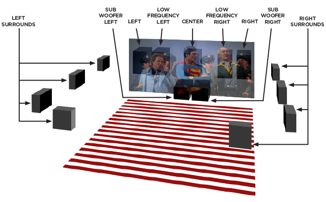
With a 70mm Dolby-Encoded “baby boom” print, tracks 2 and 4 carry this lower-pitched “boom” track information, which is handled by the magnetic sound “format” module located either in slot 18, 19, or 20 of the CP100 — just like any 70mm print. But tracks 2 and 4 were run through special “Link/Filter” cards (Catalog number 105D) in slots 21 and 22. The 105D Module contained a 200 Hz low-pass filter, providing a frequency range of 200 Hz down to 25 Hz, as well as individual equalization — presumably adjusted to make deeper sounds from the standing house speakers without blowing them to bits. We assume the Chinese was still using their five speaker array of Voice of the Theatre A2 speakers behind the screen. These speakers were rated to produce sounds as low as 30 Hz. Low indeed, but not low enough. Sensurround went down to 16 Hz with specially-designed speakers and amplifiers, but still, the 2 “baby boom” tracks provided an impressive rumble — in stereo!
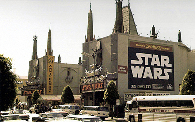
When Star Wars opened on May 25, 1977, Mann’s Chinese Theatre was one of only thirty-two theatres playing the film. Of these, only eight theatres — three in Los Angeles, four in New York and one in San Francisco played it in 70mm Dolby System. Theatres playing the picture in 70mm were required to install the Dolby equipment, which might have included better bass delivery amps and speakers for tracks 2 and 4. Only twelve theatres played the film in 35mm Dolby Stereo, while another twelve theatres played the picture in mono! Over the next two days, Star Wars opened on eleven additional screens — but none in 70mm.
Theatres playing "Star Wars" beginning Wednesday, May 25, 1977:
The concentration of 70mm Dolby in the largest markets was consistent with release patterns in 1977. If the largest groups of people who went to see the film during its first weeks saw it under the best circumstances, the larger the positive word of mouth would be created. The fewer the 70mm engagements were, the more the Star Wars crew could concentrate on customizing each theatre. The Hollywood opening of the film must have been important to both Lucas and to 20th Century-Fox, so they must have labored over how it sounded; this was no ordinary playdate.
Mann's Chinese Theatre, Hollywood, California. Exterior during engagement of Star Wars, beginning Wednesday, May 25, 1977.
Like Hell’s Angels before it, Star Wars made no mention of its “baby boom” effects; but it was there, waiting just below the surface, to blast audiences with what came to be known as “low frequency effects.” In addition to everything else which was unique about Star Wars, people came back again and again to experience the film in 70mm at the Chinese — with its huge screen, great sound system, boomy acoustics and exotic decor — the film and the theatre were a perfect match. There were other theatres in the Los Angeles market playing the picture in 70mm, but the Chinese became the shrine of the Star Wars experience, where it played for almost an entire year.
Platters Come to the Chinese
We interrupt our Dolby story at this point to make mention of the installation of platter systems at the Chinese during this timeframe. The extraordinary success of Star Wars, followed by Superman: The Movie, released at the tail end of 1978 convinced theatre owner Ted Mann (1916-2001) to build two additional “Chinese” theatres on the parking lot to the east of the building. (Not so) affectionately known as “The Chinese Twins” the two 700-seat theatres were opened with much fanfare in April of 1979.
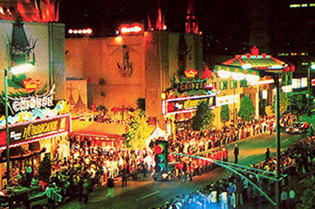
Mann's Chinese I, II, and III Theatres, Hollywood, California. Exterior during the world premiere of Hurricane, Thursday, April 12, 1979.
Part of Mann’s decision stemmed from improved box-office conditions in the post Star Wars marketplace. The other part was that Mann’s business model had been to eliminate all of the old Fox West Coast / National General theatres, building multi-screen complexes in their place. Multiplex theatres, accommodating more and more screens, had been facilitated by two technological developments pertaining to the projection room, namely, the xenon lamp and the platter system. Both of these devices would make it possible for one projectionist to run all of the projectors in a multiplex environment, and eventually to eliminate projectionists at the local multiplex altogether.
Making Projecting Films Easier
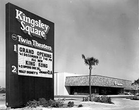
ABC Kingsley Square Twin Theatres, Orange Park, Florida. Opened December 17, 1975. Closed by 1988. Photo posted by IMakeMovies, via Cinema Treasures.
Since the xenon lamp could provide brilliant light for several thousand hours at a time, things would be a lot simpler if a projectionist wouldn’t have to change reels every 20 minutes. The Cinerama / Cinemiracle systems had both employed 10,000 foot reels, which would hold only half of their feature film runtime and were very heavy. The 10,000 foot reel could hold a short conventional 35mm feature, but that wasn't seen as practical. The industry began using 6,000 foot reels in the late 1960s, which would require only one changeover per showing, so one projectionist could run two different shows. This approach was utilized in many of the “twin” theatres which began dotting the country in the 1960s. Some of these operations installed early versions of automation — devices which would trigger changeovers, dimming lights, opening curtains and the like.
Theatre owners reasoned that having two auditoriums attached to a common concession stand, box-office and projection booth could potentially increase income without increasing labor costs. So the industry trend was to streamline operations as much as was possible. Part of what made projecting a feature film difficult was having to rewind the film after it was shown. Various companies developed projectors which would allow one “built-up” print (the entire movie spliced into one continuous roll) to be rewound on the projector while another was playing.
But it wasn’t until 1968 when Philips Electric (makers of the DP 70 projector) and their German distributor Kinoton brought out a device which would change how films would be projected forever. They called it a “non-rewind” system: the ST 200.
The Idea
In a conventional projector, a strip of film is wound onto a feed reel, so that the beginning would be on the outside. This is called “heads out.” The "head” then goes through the projector, then gets taken up on a reel below until the “tail” of the filmstrip is on the outside of that take-up reel. Then the reel is called “tails out.” In order to make the reel which is “tails out” become suitable for showing again, the film is rewound onto another reel, so that it is now “heads out” again.
So the designers thought: what if the rewinding process could be eliminated? How about building up the print for the whole movie and winding it “heads in” around a large removable ring placed in the center of a circular, rotating table? By removing the ring, the “head” of the print could be pulled from the center. Transported by rollers, the film would go through the projector as normal, then get taken up around the ring of another "platter," thereby returning the print to the same orientation it was in when starting the showing. The print essentially is wound up on a big reel with only one side (or flange), which allows removing the film from the larger, center hole.
Diagram showing normal method of winding film on the left and the "non-rewind" method involving platters on the right. Diagram by Kurt Wahlner.
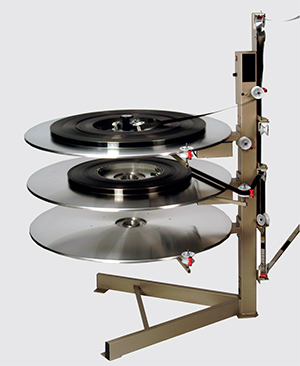
Kinoton ST 200 Non-Rewind System. Introduced in 1968. From the Kinoton brochure ST 100 E-ST 500 E Non Rewind Systems, Kinoton GmbH, Germering, Germany, September, 2010.
Since double features were common in the industry in the late 60s, three platters in a stack would allow for the storage of the two features, plus one platter for take-up of the feature currently playing.
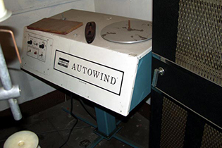
Kinoton brought this device out in 1968, and it was immediately copied by the projection equipment manufacturer Christie, of Cypress, California. The Christie brand was called the “Autowind” and was sold to many of the multiplex cinemas cropping up across America.
By 1979 when the Chinese Twin Theatres were opened, the original Chinese Theatre booth had been spared the coming of the approaching trend, showing films the old-fashioned way, with one projectionist tending the three DP 70 projectors and showing the films on 2,000 foot reels with a changeover every 20 minutes. With the opening of the Chinese Twin Theatres however, Mann Theatres was able to negotiate a new contract with the the Projectionist Union, allowing for one operator to run the projectors in all three auditoriums (unless it was 70mm, but they fixed that eventually as well). The City of Los Angeles had required theatres to have a license for projection rooms — having an operator standing by at all times — which was relaxed as well, so that the Chinese Theatre operator could tend to the machines in the Chinese Twins.
These platter systems signal a real worldwide change in motion picture presentation. It was a cost-cutting move made by the theatre owners, pretty much invisible to the average movie-goer. But the practice had many disadvantages, which profoundly alienated many movie buffs and industry people: it signalled the beginning of a gradual deterioration of presentation standards. When curtain motors broke, they were not repaired, and eventually, curtains were not installed in newer multiplexes, allowing for the practice of showing ads before a showing. Dirt and scratches were rampant, and focus was often unattended by an operator who was running 10 or more platters at one time. The platters came to rule in the nation's theatres, whereas when Hollywood showed their films to each other at the Academy Headquarters in Beverly Hills, single reel, multi-projector presentation remained. What was good for the goose was not, in this case, good for the gander.
The Christie Autowind System
The Chinese went with the Christie brand of platters — the Autowind system — in 1979. Christie had introduced their Autowind AW-1 in 1971. In 1976, the AW-2, made its debut. The Autowind consists of two parts: The makeup table and the platter column.
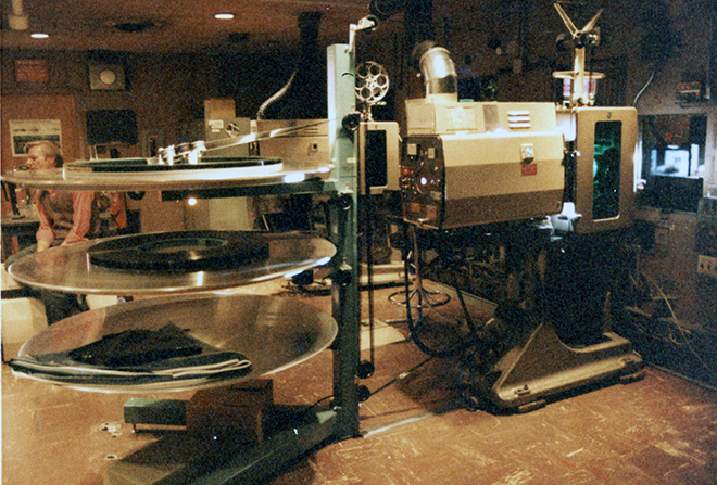
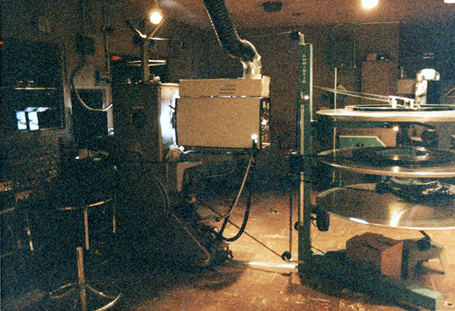
Mann's Chinese Theatre, Hollywood, California. Projection Room, 1984. Photo by Mark Gulbrandsen. Christie AW2 system, Philips / Norelco DP 70 projector and Optical Radiation Corporation ORC 6000 xenon lamphouse.
35mm print of The Thing (1982) on standard 2,000 foot shipping reels in two shipping cases. Photo via outpost31.com.
The make-up table was a small rewind bench on wheels, which allowed it to be moved from one projection station to another. Films at this period were sent to theatres in shipping cases which held the 2,000 foot reels. One reel could run as long as 22 minutes, so a two-hour feature would be on six reels. Each reel had leaders on them indicating the reel number and either “head” or “tail” so that operators would know if a reel was "heads out" or "tails out." Projectionists were asked to return reels to the shipping case “heads out,” and this became even more important now.
The goal is to take the reels and to wind them onto the ring at the center of a platter table in one continuous roll from head to tail — without the leaders for each reel. Placing each 2,000 foot reel on the spindle of the make-up table, one would take the head of the first reel, and, after adjusting the height of a roller on a pole attached to the corner of the unit, wind it around the ring on a platter. When the tail of that reel would appear, the tail leader would get cut off and stored someplace. Then, the head leader of the next reel would get cut off with the first frame being spliced next to the last frame of the previous reel. Then the rest of the reels were “built up” in that manner until the end, where the tail leader of the last reel would be retained.
The studios had to correct for the gap between the picture and the sound once platters became standard: because the sound is ahead of the picture, the sound from the finishing reel would stop 21 frames ahead of the picture. The print had to be built up on the picture frames and not the sound, so it became industry practice to place the first 21 frames of the sound for the next reel at the tail of the last reel to cover the difference. This was known as a “married” print.
The make-up table was used to “break down” the built up print for shipping to the next playdate. Once a print was finished at a multiplex, an operator had to reverse the process, returning the print to its 2,000 reel lengths and re-attaching all of the head and tail leaders. After a time, theatre managers and other non-projectionists began doing this process, resulting in many hilarious mistakes — which would be shipped along to the next playdate — Oops!
Christie Autowind MK-35 make-up table. Introduced in 1971. Photographed in the projection room of the Capitol Civic Center Theatre, Manitowoc, Wisconsin by Racheal Gilardi, 2004, via Film-Tech.com.
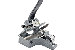
Christy's Tape Splicer, introduced circa 1965. Photo from Christy's Editorial, Burbank, California.
With the introduction of the tape film splicer, the splicing process became much simpler. So simple in fact, that splicing could be done imperfectly, and they would still hold and run through a projector. But they were hard to unmake — the tape did not come off the film easily. Operators doing the make-ing up would want to cut the leaders off on the first frame with no tape on them, so with each build-up, more and more of the head and tail of reels would get cut off, flipped, and so on. The process opened the door to many errors.
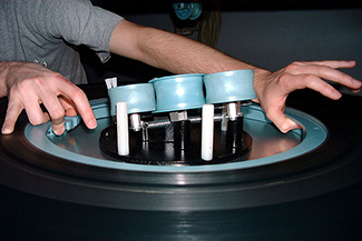
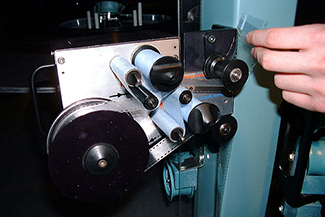
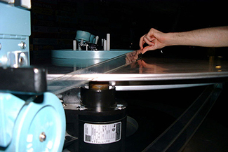
In the platter tower, there were three platter levels — two for holding films to be played, and one to perform takeup. Some systems offered 5 platters so that one could run double features in twin theatres without having to purchase another unit. The Christie platters were made of aluminum, with each one having its own motor. A table could accommodate 24,000 feet of 35mm film (4 3/4 hours) or 21,000 feet of 70mm film (3 hours). Once a print had been wound around the center ring, the ring had to be pulled out, then, the film had to be threaded through the “brain” a collection of rollers which controlled pulling the film out of the center. Essentially the brain would react to the tugging of the film to alter the rotational speed of the platter, allowing the film to become unwound without snapping.
Once the print is built-up around the ring, catches release it, so that it may be lifted straight up.
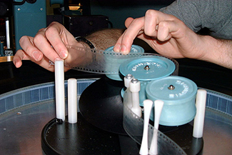
Then, the head leader is threaded through the "brain" located in the center of each platter level.
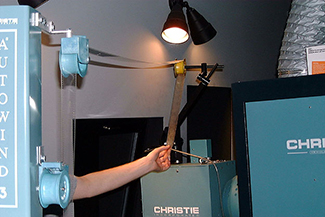
The film travels over to the rollers on the "tree." Depending on which rollers are used, the film travels to the different platter levels.
While moving up and down the tree, the film could pass through a film cleaner. The Chinese did not have one.
The film travels up the tree, hits the top roller, then over to the projector.
Once out of the projector, the film goes up and down the tree, until it reaches the proper platter level, where it is wound around another ring. Repeat.
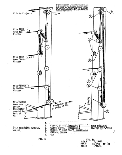
Figures 5 and 5-A, showing threading of film through tree rollers of the Christie AW2 Autowind System. From Operator's Manual Autowind 2 Film Handling System TD-194, published by Christie Electric Corporation, 1976. Via Film-Tech.com. If you had to look after 26 of these at a time, you would get good at memorizing these paths.
Once the film was threaded up and running, an operator could walk away from the unit, so that if a splice was out of frame or the film broke, or if the picture got out of focus, it was usually up to an audience member to go out to the lobby and convince someone at the concession stand that things had gone awry. Since the platters subjected film to more air, the static electricity inherent in all of this would attract dust to the film. To counteract this, Christie made a “film cleaning” module, which could be hung on the tree, removing dust with a gentle swipe from a cleaning agent before going into the projector. A great idea, but the Chinese did not have one.
In order to have one operator (who may or may not be a projectionist) work all three Chinese Theatres at the same time, an automation system of an unknown make was installed. By placing tape triggers on the print, one could tell the system to do a number of things which had been done by hand previously: close the curtains, bring the house lights up and close the dowser at the end of the film. Many’s the time when a moviegoer would see the entire tail leader play through a projector, then white light, suggesting that someone or something had let the film run out. Once automation systems became computerized in the mid 1980s, things became more elaborate, with lights coming on as the end credits began, running the slides before a show, running trailers way louder and a plethora of things no self-respecting projectionist from the old days would ever consider doing.
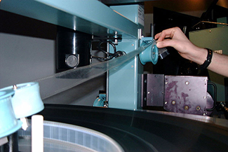
When it came to be time to move a built-up film from the platters in the Chinese I, and to move them to the Chinese II or III, the last showing would be taken up with a round masonite covering on the takeup platter. When the time came to make the move, you would remove the ring from the center, then you would get one of the guys working late at the candy counter to help you lift the print off of the platter, and carry the thing from the booth, over to the east side exit alley, where there was a doorway leading to stairs, which went up to the booth of the twins. This was the only route between the two buildings.
Mann's Chinese Theatre, Hollywood, California. Projection Room, 1984. Photo by Mark Gulbrandsen. Philips / Norelco DP 70 projector, Optical Radiation Corporation ORC 6000 xenon lamphouse, and Christie AW2 system with MK-35 Make-up Table in the background.
The Chinese would be loyal to the Christie brand, installing an AW3 in 1998 and retaining it until the IMAX® remodel in 2013. They would install Christie Digital projectors in late 2003, and upgrade them to 4K units in 2013, which remain on duty to show non-IMAX® films today. Now, back to our Dolby story. . .
Dolby Introduces the CP200
Star Wars had made Dolby a household name. Producers wanted those high calibre soundtracks for their upcoming space operas, while theatres were clamoring for the gear to run them. Everyone smelled money, because it was a fact that moviegoers were reacting to these greatly expanded soundscapes with increased patronage. The theatres which could provide the proper sensations, the “more bang for the buck," would get the “repeat” business: Viewers who would see a film over and over. With the studios now beginning to release films to the "home video" market (VHS and BetaMax VCRs), it was vital for theatres to remain superior to watching films at home. Dolby Labs equipment was central to bringing customers in. As good as 35mm Dolby Stereo was, 70mm Dolby Stereo was better.
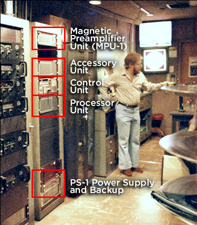
Mann's Chinese Theatre, Hollywood, California. Projection Room, 1984. Photo by Mark Gulbrandsen. The rack in the center of the three racks contains the new Dolby CP200 Units.
This gave rise to an increased use of the 70mm format. The Dolby “baby boom” format for films like Star Wars and Superman: the Movie caused even period pictures like Hurricane to want that 70mm sound. Motion picture labs responded to the increased demand by developing a polyester base for release prints. These much stronger prints could withstand the increased wear and tear the new 70mm platter systems subjected them to.
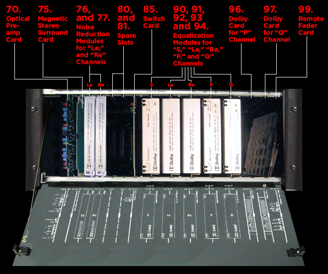
But as we have seen, in order to run the 70mm “baby boom” prints with full noise reduction and equalization, the Dolby CP100 Processing unit had to be added on to. What was needed now was a newly designed unit which would be capable of handling all the new formats which had been created, including the new 70mm “split surround” developed for Superman: the Movie (which will be detailed below). The answer: the CP200, introduced in the Summer of 1980.
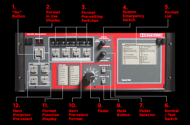
The CP200 now consisted of several rack-mounted units, all in gray with red trim. Firstly, there was the Control Unit, which was the command center; this was where you set up the pre-selects, and it gave out status readings.
Then there was the Processing Unit, which recieved the low-level signals from the projectors and performed basic processing, such as SVA and noise reduction decoding. In addition, more noise reduction and equalization modules could be contained in another box, which was called the Accessory Unit. Preamps for magnetic tracks were contained in a separate box, called the MPU-1 or Magnetic Preamplifier Unit. All of these units were tied together and powered by a separate PS-1 Power Supply, and optional backup power supply (the Chinese installed all of these units, as did most theatres equipped to play 70mm Dolby Stereo). Dolby recommended the positioning of the units in a rack; Processor Unit below the Control Unit with the Accessory Unit above, the MPU-1 should be above and separated from the others, while the PS-1 Power Supplies were to be kept as far from the others as possible.
Basically, the CP200 could handle most of the things that were going on in the exhibition world at the time. You could control the units via remote control. You could have two projectors connected or only one. Most importantly, it offered “bass extension” for 35mm SVA optical tracks, which would send low frenquency effects (LFE) below 100 Hz to whatever you were using for subwoofers via a dedicated output.
The CP200 was the first Dolby Stereo unit which allowed for dedicated LFE outputs for subwoofers.
The advances made in the CP200 are noteworthy, when it is recalled that the Apple II personal computer (with its slots for removable function cards) had only been on the market for a few years. Consumer electronics were beginning to influence professional designs and vice-versa. Among the improvements:
Format selection with memory allowing push button switching between pre-set formats
Allows for inputs from up to four projectors.
Allows for considerable capability expantion, based on specific needs.
Remote control panels may be located at each projector for instant control.
Eight main outputs (five stage channels, one for mono surrounds, and two for stereo surrounds)
Dedicated subwoofer output for Optical Bass Extension from 35mm SVA optical and 70mm.
No external adaptor required for 35mm surrounds.
Improved 35MM SVA surround decoding with the new catalog number 150 card (33)
Rated to operate up to 104 degrees farenheit.
Provides power to the MPU, which can accommodate inputs from two 70mm projectors each; two MPU-1s may be used for four projectors. Changing projectors can be done with the "Go" button (1)
Allows instant flipping between outermost 70mm stage speakers (Left and Right) to the "Extra" speakers closer to the center (Left Extra and Right Extra). Low Frequency signals flip also.
Split surrounds accomplished without the use of external units.
Ample slots for noise reduction and equalization for all six 70mm magnetic tracks.
1. "Go" Button: Changes mode of the CP200 into format and projector selection pre-selected with buttons (10) and (12).
2. Format in Use Display: Numeric LED readout display shows actual format in use. Display flashes if format selected by (3) has not been programmed into the CP200.
3. Format Pre-setting Switches: Four pairs of numerical switches for pre-setting formats used during a showing (trailers, feature, etc.).
4. System Emergency Switch: System Emergency Switch bypasses signal processing in case of failure.
5. Format List: List of code numbers for commonly used formats to aid in setting switches (3).
6. Normal / Test Switch: Used during setup and maintenance procedures.
7. Fader Selector: This button selects the control panel fader (9) or a remote fader.
8. Mute Button: automatically fades signal over 3-second period; a second press (or pressing the “Go” button (1) cancels this fade, returning to level set by fader controls).
9. Fader: Master fader for all eight channels.
10. Next Pre-select Format: These buttons set the formats displayed above. The "Go" button (1) scrolls through the pre-selected formats.
11. Format Function Display: Tally lights show which functions (mono, surround, noise reduction, etc.) are being used in the format in use.
12. Next Projector Pre-select: These buttons are used to select the projector used when switching between formats.
Dolby Laboritories Cinema Processor Model CP200, Control Unit. Introduced in summer 1980. 19 inches wide x 7 inches high x 11 inches deep; 15 pounds. Offered for sale by eBay seller industrial-assets.
45. Format / Projector Logic Card: Logic circuits which interpret position of front panel controls (Catalog number 156).
46. Fader / Mute Logic Card: Circuitry for local and remote fader selection, and for mute feature (Catalog number 157).
47, 48, 49 and 50. Format Decoder Cards: Cards decode selected front panel format switches; supplied pre-wired and identified for optical, 35mm mag, 70mm mag and non-sync. Each card contains switches to allow special formats to be set up (Catalog number 153).
51 and 52. Bus Driver Cards: Power drivers which transmit information from decoder cards (47) - (50) to drive the various control lines in the CP200 (Catalog number 154).
53 and 55. Remote Fader Cards: Fader card containing remotely controlled four-channel fader. Fader action is a single dc control (local or remote) feeding all four electronic faders which track to ±1 dB in their working range. Four present controls allow individual setting of the output levels to suit the power amplifiers in use. Module contains two output amplifiers (Catalog number 117).
54. Ouput Card: This card contains four output amplifiers. The complete package of two catalog number 117 cards and one catalog number 137 provides eight channels of faders and output amplifiers (Catalog number 137).
56, 57 and 58. House Equalizer Modules: Three cards containing 27-band 1/3 octave filters to provide optimum frequency response for Left, Center and Right channels (Catalog number 64).
Dolby Laboritories Cinema Processor Model CP200, Control Unit with front panel opened. Introduced in summer 1980. 19 inches wide x 7 inches high x 11 inches deep; 15 pounds. Located in the projection room of the Warner Grand Theatre, San Pedro, California, 2013. Photo by Bill Counter.
20. Optical Pre-amp Card: Optical Pre-amplifier card with inputs for two projectors for use in playback of mono or stereo optical films using suitable stereo cells. Contains four pre-amplifiers for the two channels of the two projectors, each with front-accessed adjustment of gain and high frequency (Catalog number 108).
21. Magnetic Input Card: Contains inputs for switching for two projector/6 or 4 track magnetic systems (Catalog number 201).
22. Non-Sync Input Card: Has amplifiers and switching for three stereo inputs and a mono mic input. Also contains bypass amplifier used in emergency situations (Catalog number 143).
23, 35, and 37. Switch Cards: Contains three pairs of electronic two-pole, four-way switches to select and route signals in CP200 (Catalog number 141).
24, 25, 26, and 27. Noise Reduction Modules: Four noise reduction modules (NRM) which are used to decode the Left, Center, Right and Surround channels from either SVA or magnetic source. (Catalog number 22).
28, 29, and 30. Meter / Filter Cards: Meters which indicate the signal level in all channels, and are used for setting up Dolby Level using special Dolby Tone film loops. Card also includes precision Academy filter which is switched in automatically when non-Dolby film is selected (Catalog number 109C).
31, and 34. Link Cards: These spaces are provided for future developments; the link card ensures signal continuity (Catalog number 207).
32. Optical Bass Extension Card: This card extracts low frequency signals from optical film for use with the normally unused Le and Re amplifier and speakers. The card also contains separate controlled outputs for a sub-woofer system if one is installed in the theatre (Catalog number 160).
33. Decoder Card: The decoder consists of a Catalog number 146 decoder and a delay sub-assembly on the same card. This card decodes Dolby SVA optical tracks into left, center, right and surround channels (Catalog number 150).
36. Equalizer / Filter Card: Two-channel low pass filter to extract low frequency signals from Dolby magnetic 70mm soundtracks. Special circuits remove the usual low frequency resonances of the speaker / auditorium combination (Catalog number 142).
Dolby Laboritories Cinema Processor Model CP200, Processor Unit with front panel opened. Introduced in summer 1980. 19 inches wide x 7 inches high x 11 inches deep; 15 pounds. Located in the projection room of the Odeon West End Cinema, London, England, 2008. Photo posted by JBLsound4645 on avsforum.com.
When it comes to detailing the inner workings of the CP200 Accessory Unit, it is useful to bear in mind its inclusion of the 70mm "split" stereo surround format, which has not been discussed in this survey — yet. The Chinese did not play a 70mm film with stereo surrounds until later.
70. Optical Pre-amp Card: Optical Pre-amplifier card with inputs for two projectors for use in playback of mono or stereo optical films using suitable stereo cells. Contains four pre-amplifiers for the two channels of the two projectors, each with front-accessed adjustment of gain and high frequency. This replication of slot (20) in the Processor Unit allowed for the use of four projectors (Catalog number 108).
75. Magnetic Stereo Surround Card: With Format 43 (stereo surrounds in 70mm) selected, separates track 2 and 4 into two catagories: Below 500 Hz goes to the Left Extra and Right Extra "boom" speakers, while above 500 Hz goes to the Left and Right Surrounds. (Catalog number 158).
76, and 77. Noise Reduction Modules: Noise reduction for Left Extra and Right Extra channels. Sent to (75) Magnetic Stereo Surround Card if Format 43 is selected (Catalog number 22).
80, and 81. Spare Slots: Provided for future additional cards or for replacing bad slots in the Accessory Unit??? No "Link Card" needed (see 31 and 34 in Processor Unit).
85. Switch Card: Flips position of Left and Right speakers to Left Extra and Right Extra, and vice versa, for 1:1.85 films (Catalog number 213).
90, 91, 92, 93, and 94. Equalization Modules for "S," "Le," "Re," "P," and "Q" Channels: Equalization modules for for Left Extra and Right Extra, and for the surround channels: "S" for mono surround, "P" for Left Surround and "Q" for Right Surround (Catalog number 64).
96, and 97. Dolby Cards for "P," and "Q" Channels: Thumbwheels on these cards set the time delay for each channel (Catalog number 214).
99. Remote Fader Card: Drives remote fader information on remote unit (Catalog number 117).
Dolby Laboritories Cinema Processor Model CP200, Processor Unit with front panel opened. Introduced in summer 1980. 19 inches wide x 7 inches high x 11 inches deep; 15 pounds. Location and date unknown.
The Next Step: Stereo Surrounds for Dolby 70mm
Gordon K. McCallum at the BAFTA Awards for 1974 in London, England, receiving his award for his work on the film Jesus Christ Superstar.
For the next development in the Dolby story at the Chinese, we have to backtrack a bit.
Star Wars began a trend of films calling for greater sophistication in what came to be called “sound design.” Films of a sci-fi / fantasy / superhero subject matter were suddenly rushed into production with large budgets, requiring big everything — including soundtracks. Father and son producers Alexander and Ilya Salkin had been trying to get a film based on the Superman comic book character “off the ground” for several years, but now, after the success of Star Wars, Warner Bros. was hot to get it done on as large a scale as possible.
The production, based at Pinewood Studios in the UK, had selected legendary soundman Gordon K. McCallum (1919-1989) to be in charge of the sound department and would be the film’s final mixer. McCallum told Pinewood sound head Geoff Labram and Max Bell (b. 1940), Dolby’s consultant liaison with the filmmakers, that he wanted to have stereo surrounds for the 70mm prints of Superman the Movie.
Since the upper frequency range of tracks 2 and 4 were not being used, it was decided to designate a crossover point at around 500 Hz, and have the tracks carry higher frequency right and left surround effects, encoded with Dolby A noise reduction. To aid in separating signals which were intended to go to the subwoofers from those intended for the surrounds, a “slope” was created, so that the low frequency signal would decrease in volume as its frequency rose toward the crossover, while the effects channel would do the opposite: decrease the signal as it dropped below the 500 Hz crossover. Seems simple enough. The problem was that Superman the Movie was facing a grueling release date deadline. The 70mm prints would have to be 100% compatible with the 70mm “Baby Boom” format.
Dolby Stereo 70mm Split Surrounds (Format 43) therefore works like this: Tracks 2 and 4 would contain low frequency effects below 200 Hz, and left and right surround effects above the 500 Hz crossover, which are given Dolby A noise reduction. If you had the Format 43 module in your CP 200, you would have the split surrounds, and if not, nothing. Track 6 contained a mono mix of the left and right surround effects material found on tracks 2 and 4, which plays as per normal in Format 42.
Northpoint Theatre, San Francisco, California. Exterior during the run, from Friday, December 15, 1978, of Superman the Movie. Photo from Dolby Stereo Surround On 70mm, by John Iles. Published on In70mm.com. The Northpoint would be the only theatre in America to play the film in 70mm with stereo surrounds.
Additionally, the low frequency effects on tracks 2 and 4 would now be divided as well. Sounds between 200 Hz and 100 Hz would go to the woofer of your stage speakers, while those below 100 Hz would now be sent to your subwoofers through a dedicated subwoofer output on the CP200.
For Superman the Movie, Dolby engineers John Iles and David Watts built the appropriate 8 channel recording and monitoring gear and aligned the mixing room at the studio. Technicolour in London under Jim Winterborne made the 70mm prints. Superman the Movie became the 50th film to be produced using the Dolby Stereo system with type A noise reduction, and would play in that format in over 200 theatres in the United States. The Dolby thing was catching on!
While Superman the Movie played at the Chinese Theatre in December 1978, the split surround format module was not available yet. The Dolby folks set up Format 43 at the Northpoint Theatre in San Francisco, not far from their home office, and supposedly did the same for the AMPAS Samuel Goldwyn Theatre in Beverly Hills for the Oscar screenings (the film would be nominated for best sound, but would loose out to The Deer Hunter). The first film to have a wider release in Format 43 would be Apocalypse Now, released in August of 1979, which began its run exclusively in 70mm with Dolby split surrounds.
Mann's Chinese Theatre, Hollywood, California. Exterior during the run, from Thursday, December 14, 1978, of Superman the Movie.
Mann's Chinese Theatre, Hollywood California. Exterior during the run, from Friday, May 16, 1986, of Top Gun.
Although Format 43 created for the first time what would eventually become known as "5.1" sound layout in the digital sound realm, the extra work and costs involved with creating films in the format caused it to be used on only the biggest films. They were marketed to the public as 6-Track Dolby 70mm.
* Superman the Movie played the Chinese, but not in Fortmat 43.
** Days of Thunder was to play in the CDS digital format, but technical problems resulted in the analog Format 43 to be used instead.
Incredible as it sounds, the first film to play the Chinese in Format 43 was the Tom Cruise epic, Top Gun, which ran for a whole week in May, 1986.
VistaSonic Sound and Popeye
Amongst all the new ideas hovering around to improve movie sound, yet another approach to getting full-range 5-track sound out of a 35mm optical print was brought out in late 1980.
VistaSonic sound was developed by Terry Beard, who was working in Paramount’s sound department as a researcher. Beard had been running a company called NuOptix, which specialized in making equipment used in making optical soundtracks for films, so he knew something of their limitations and what Dolby had done to overcome them.
In the Dolby Stereo system, a very high range of frequencies were compressed into the more limited range of two “bilateral” variable area optical tracks. These were then “decoded” by logic circuitry in a dedicated processor to separate out left, center, right and surround channels. Since Dolby got four channels of sound out of two (SVA), Beard thought: why not use four discrete variable area optical tracks to get four channels of sound?
Trouble was: the thinner the track on the film, the more limited the dynamic range and output. Thinner optical tracks would naturally reduce the dynamics it could carry. They wouldn't be as loud either; to turn the volume up would also increase the background noise. Beard and his crew were forced to compress the full range of sounds into the even narrower capacity of the thinner tracks. While doing this, “split” or stereo surrounds were added to the format by “matrixing” left and right surround info out of phase on the left and right optical tracks via Sansui’s QS Matrixing system. This allowed them to reduce the number of optical tracks down to three — making them wider helped increase the dynamic range and output of the tracks.
The tracks were read by a special sound head placed above the projector head as when magnetic stereo prints were first introduced. Since hardly any projectors had "feed reels" anymore because of the platter systems, the reader could be plopped on top of the Norelco's at the Chinese, and adjust the delay until it was in sync. Light streaming through the optical tracks fell upon CCDs — microchips which turned the light received into electrical impulses. The alignment of lamp, soundtracks and CCDs was critical, as any misalignment would wreak havoc on the CCDs ability to read the tracks. We do not know what was used for noise reduction; dbx probably.
And havoc was certainly served up at the Chinese on the night of Saturday, December 6, 1980, when the World Premiere of the first film to use the system, Popeye, began. There are no eyewitness accounts (or should we say "earwitness"?), but legend says that the sound system “failed” in some way during the first reel, forcing the use of a mono backup print for the remainder of the showing. Although Paramount had the system used to mix the upcoming Dragonslayer and Raiders of the Lost Ark, both of these films re-giggered their mixes and went out with Dolby Stereo tracks. Better luck next time.
The Chinese and the THX Certification Program
Mann Chinese Theatre, Hollywood, California, during the engagement, beginning Friday, February 3, 1989, of the film Her Alibi, showing the THX logo.
With the introduction of the Dolby CP200 System in 1980, theatre owners across the world could now install what looked like an industry standard for all the Dolby Stereo films coming out of Hollywood at an astounding rate. Mono films were still being released, but it was becoming more rare.
Also around 1980, George Lucas began to become aware of the fact that his Star Wars: The Empire Strikes Back film was being shown across the country in a big rag-tag collection of theatres. Some were big old barns from the 1920s with the hard acoustic surfaces demanded in live theatres, while some were small multiplex shoebox theatres, struggling to keep the sound inside the one house without it bleeding into neighboring shoeboxes.
Additionally, with the rise of the home video market, producers and the studios began to streamline their operations for film soundtrack elements. No one wanted to pay for a theatrical mix and a home video mix if they didn’t have to. Since Dolby Stereo made four channels out of two, this was perfect for VHS tapes, which had two channels. In order for a film to sound good in your living room, the same mix would have to sound good in the local movieplex — and so the acoustics at the theatre became more like a living room — pretty dead acoustically.
Lucas began thinking of a way to standardize the way films sounded in theatres. Knowing about the Academy Curve introduced in 1938, Lucas envisioned a program where a given theatre would install state-of-the-art amps and speakers, but also certain structural modifications in order to ensure similar acoustics in all the theatres in the program. All of this qualified a theatre to be “THX Certified.” THX Certification came to mean to audiences that the theatre would have the very best in sound systems.
Tom Holman
In order to make this certification program possible, Lucas turned to sound wunderkind, Tom Holman (b. 1946). Tom is the “TH” in THX. Originally a theatre buff, Tom turned to sound design for the theatre as well as film, while attending the University of Illinois. Graduating in 1968, Tom worked at the U on various publicity films the University needed. Reading about sound equipment being developed during that time, Tom ordered it all for the University, so he had lots of toys to play with.
But he felt it was dead end. In 1973, Tom went to work at Henry Kloss’s Advent Loudspeaker Company in Cambridge, Massachusetts. Advent had become very successful with their introduction of the 2-way speaker with a 10-inch woofer called The Advent Loudspeaker. Although working at Advent was interesting for Tom, he set up his own company, Apt, in 1977 — the same year as Star Wars. Apt made amps and pre-amps for the home stereo market. The Apt Corporation Power Amp 1 was considered a very pure-sounding unit, so pure that it caught the attention of George Lucas, who invited Holman to join his company in 1980 — same year as the release of The Empire Strikes Back. Holman, trained in “high fidelity,” felt that he could make a real contribution in upgrading film sound systems in theatres.
Tom Holman. From Speaker Builder, September/October, 1990, '"Tom Holman, Skywalker and THX, Part 2" by Reid Woodbury, Jr.
The Advent Louspeaker. Introduced in early 1971, 25.5" tall x 14.25" wide x 11.5" deep. Photo by Goody Music, Rome, Italy.
Apt Coporation, Holman Preamplifier, and Power Amplifier 1. Introduced in 1977. Photo by orignimbo via Photobucket.
We intend to continue with the THX section — someday.